|
|
|
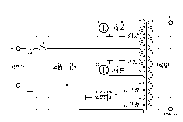
| 本電路是由Trip-Lite "Power-Verter" PV200 DC-AC換流器成品──提供電池為唯一的電源的露營或遊艇活動應用的典型的裝置,重繪而成。此型的額定功率為連續200W,輸出為60Hz方波但沒有安定化與準確的頻率控制。
|
This circuit was reverse engineered from a Trip-Lite "Power-Verter" Model PV200 DC to AC Inverter - typical of those used for camping or boating applications where the only source of power is an auto or marine battery. This particular model is rated 200 W continuous. The output is a 60 Hz squarewave and there is no regulation or precise frequency control. |
| 改變輸出電壓是相當容易達成的。例如高速週期閃光燈需要330VDC,只需要將輸出繞組的圈數三倍後,加上橋式整流器為儲能電容器充電即可。另外,此換流器也可以視需要加上一三倍壓器一起工作。是三倍壓器,不是二倍壓器,因為它是方波輸出。(均方根值與峰值相同,所以不會像使用電力公司的正弦波交流一樣得到1.414倍的提昇。) | Modifications for higher or lower output voltage are easily achieved. For example, a fast cycle strobe requiring 330 VDC, would only require using three times the number of turns on the Output winding and the addition of a bridge rectifier to charge the energy storage capacitor(s). Alternatively, the inverter could be used as-is with the addition of a voltage tripler. A tripler rather than doubler is needed because of the squarewave output. (The RMS and peak voltages are the same so you don't get the boost of 1.414 as you do with the sinusoidal waveform from the power company.) |
 |
|
| 電力換流器註解
1. 原電路為搭棚製作──沒有電路板。如有需要,電路板規劃的要求並不嚴苛。 |
Notes on the power inverter
1. Construction was all done point-to-point - there is no circuit board. Layout appears not to be critical. |
| 2. T1是一個大型的E-I變壓器。E片與I片交錯排列以形成一低洩漏的磁路。 | 2. T1 is a relatively large heavy laminated E-I core transformer. The E and I sheets alternate direction to assure a low reluctance magnetic circuit. |
| 整個鐵心的尺寸為33/4"*31/8"*11/8",鐵心的外磁路寬度為5/8",內磁路寬度為1",繞線軸直徑為13/8"。 | The core dimensions are 3-3/4" x 3-1/8" x 1-1/8" overall. The outer legs of the core are 5/8" thick. The central leg is 1" wide. The square bobbin has a diameter of 1-3/8". |
| 360圈的輸出繞組首先捲繞,其中間隔4~5層絕緣片,再來是31圈驅動和17圈回授繞組。各繞組間夾有一絕緣片。 | The 360T O (Output) secondary is wound first as 4 or 5 insulated layers followed by the 31T D (Drive) and 17T F (Feedback) windings. There are insulating layers between each of the windings. |
| 各繞組圈數為未拆解變壓器之估計值,如下: | The number of turns were estimated without disassembly as follows: |
| •各線號以將可視部分的線頭對照已知線號之漆包線或直接在可能處以測微計量得。(實際上,驅動繞組是用方形橫斷面的漆包線捲繞以得到最大包裝密度。估計此線應相當於#13AWG圓形漆包線。) | * The wire sizes were determined by matching the diameters of the visible ends of the wire for each winding to magnet wire of known AWG and/or measuring with a micrometer where possible. (The Drive windings are actually wound using square cross-section magnet wire for maximum packing density. This was estimated to be equivalent to #13 AWG round wire.) |
| •輸出繞組的圈數是由其阻抗、繞阻直徑和線規表所決定。 | * The number of turns in the Output winding was determined based on its measured resistance, core diameter, and the wire gauge tables. |
| •當換流器工作時,測量各繞組的訊號振幅,由各振幅比例可求得其圈數。 | * The inverter was run and the amplitudes of the signals on each winding were measured. From these ratios, the number of turns were calculated. |
| 3. 電晶體被標記為"69-206"。ECG29是一個比較接近的配對──高功率放大開關──80V, 50A, 300W, hFE 20min。2SD797是另外一種容易取得而能夠工作的功率電晶體。如要使用PNP晶體,則倒轉電池、C1、C2和C3的極性。 | 3. The transistor were marked 69-206. ECG29 is a close match - high power amplifier switch - 80 V, 50 A, 300 W, Hfe 20 min. 2SD797 is another readily available power transistor that should work. For PNP types, reverse the polarities of the power supply, C1, C2, and C3. |
| 電晶體裝置在作為機箱側板的散熱片上。 | The transistors are mounted on heat sinks which form the sides of the case. |
| 4. C3與R3為電路啟動所必需。因為除了回授繞組之外,沒有其他的基極電流源,當電源開關閉合時,此網路將提供一啟動脈波。若逐漸提昇電源電壓而不使用電源開關,將無法活化換流器。 | 4. C3 and R3 are required for starting. Since there is no source of current for the bases of the transistors other than the Feedback windings, this provides a starting pulse to Q2 when the unit is switched on. Ramping the input voltage slowly rather than using the power switch would likely result in the inverter behaving like an inanimate object. |
| 5. 測試出來的工作頻率約為56Hz。這幾乎被所有東西所影響──輸入電壓、電容量、鐵心磁飽和、月亮的盈虧...因為如此,所以別想用這個東西準確地驅動交流計時器! | 5. Measured frequency of operation was about 56 Hz. This is likely affected by nearly everything - input voltage, capacitance, core saturation, phase of the moon, etc. Therefore, don't expect to drive a clock mechanism from this thing with any accuracy! |
| 6. 對於零件數值的實驗將可以改善其在您的應用上的表現。 | 6. Some experimentation with component values may improve performance for your application. |
| 7. 測試時,使用一可變電源供應器將使你知道輸出電壓與輸入電壓的關係。零件數值的要求並不嚴苛,但改變輸出入電壓和負載情況下的表現將被C2、C3、變壓器繞阻圈數和電晶體的增益所影響。有關啟動請見第三點。 | 7. When testing, use a variable power supply so you get a feel for how much output voltage is produced for each input voltage. Component values are not critical but behavior under varying input/output voltage and load conditions will be affected by C2 and C3, the number of turns on each of the windings of T1, and the gain of your particular transistors. However, See note (3) about starting. |
| 8. 警告:輸出為危險的高壓──若您提昇其輸出給高壓應用電路則電壓將會更高。連續輸出超過200W是可以的。請使用適當的預防措施。 | 8. WARNING: Output is high voltage and dangerous - even more so if you increase its output for true HV applications. Over 200 W is available continuously. Take appropriate precautions. |